In modern industrial automation, advanced control systems govern environments where hardware or software failures can jeopardize human life, inflict heavy property damage, or cause environmental disasters. Treating safety as an isolated, late-stage checkbox frequently results in severe architectural flaws, failed compliance audits, and expensive project delays.
Achieving reliable risk reduction requires implementing a structured framework: functional safety (FuSa). Functional safety focuses on ensuring that safety-related electrical, electronic, and programmable electronic (E/E/PE) systems operate correctly in response to specific inputs. This master guide deconstructs the overarching lifecycle requirements of industrial functional safety compliance, utilizing the foundational standard IEC 61508 to transition safety from a regulatory burden into a core strategic design feature.
Defining the Core Pillars of Industrial Functional Safety
To systematically mitigate risk, engineering teams must understand the core parameters that define an automated safety function. An automated safety loop relies on three distinct subsystems working in perfect alignment.

Systematic Capability
Systematic compliance governs the overall engineering process. Systematic failures are caused by human errors during design, incorrect requirements definitions, software bugs, or flawed manufacturing processes. Mitigating these errors requires strict adherence to structured development lifecycles, comprehensive independent audits, and meticulous verification and validation protocols.
Hardware Safety Integrity
Hardware compliance addresses random, physical hardware failures, such as a component short-circuiting due to thermal degradation over time. Unlike systematic errors, random failures can be statistically predicted. Hardware integrity is managed via architectural constraints, such as physical component redundancy, and continuous diagnostic coverage designed to automatically detect dangerous faults.
The IEC 61508 Safety Lifecycle Framework
The master standard IEC 61508 organizes functional safety management into a strict, 16-phase lifecycle. This structured lifecycle ensures that every automated safety system progresses seamlessly from initial conceptual evaluation through long-term field maintenance.

Phase 1 to 3: Analysis and Boundary Definition: The lifecycle begins by establishing the exact physical and environmental boundaries of the Equipment Under Control (EUC). Once defined, a formal Hazard Analysis and Risk Assessment (HARA) is conducted to identify potential systemic dangers, operational failure modes, and the baseline unmitigated risk of the application.
Phase 4 to 8: Safety Requirement Specification and SIL Allocation: The safety requirements derived during the analysis phase are formally documented. Every identified safety function is assigned a target Safety Integrity Level (SIL), ranging from SIL 1 (lowest risk reduction) to SIL 4 (highest risk reduction).
Phase 9 to 11: Realization and Architecture Engineering: During realization, engineering teams design the system architecture to meet the allocated SIL targets. This phase requires analyzing component-level failure rates, establishing interface control metrics, and engineering robust communication channels across all subsystem boundaries.
Phase 12 to 13: Validation, Commissioning, and Final Audit: Before the automated system goes live into active production, it undergoes exhaustive validation testing. Independent functional safety audits are performed to verify that the physical assembly and control logic perfectly match the documented design requirements.
Phase 14 to 16: Operation, Maintenance, and Modification: Compliance does not end at installation. Over the operational life of the system, teams must perform routine proof testing to catch unrevealed dangerous failures. Any future system modifications or component replacements must be re-routed through the lifecycle to ensure the original safety case remains completely valid.
Methodologies for Functional Safety Analysis and Verification
Moving a system through the safety lifecycle successfully requires utilizing analytical tools that challenge engineering assumptions and quantitatively verify risk reduction targets.
Failure Mode and Effects Analysis (FMEA)
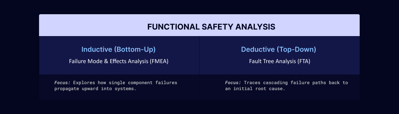
FMEA is a bottom-up, inductive methodology. Engineers evaluate each individual component within a system, list all its possible physical failure modes, and determine the direct downstream impact of those failures on the broader system. This analysis identifies hidden single points of failure and establishes the specific diagnostic coverage parameters required to detect internal component faults.
Fault Tree Analysis (FTA)
In contrast, FTA is a top-down, deductive methodology. It begins with a predefined, catastrophic top-level event and uses logical gate structures to map out every possible combination of hardware failures, software faults, and human errors that could trigger that event. FTA allows safety teams to identify common-cause vulnerabilities, where a single systemic failure might compromise multiple independent safety channels simultaneously.
Quantitative Metrics for Performance Verification
To claim compliance with a target Safety Integrity Level, the automated safety functions must be verified using quantitative reliability data. This verification relies on tracking specific mathematical failure distributions:
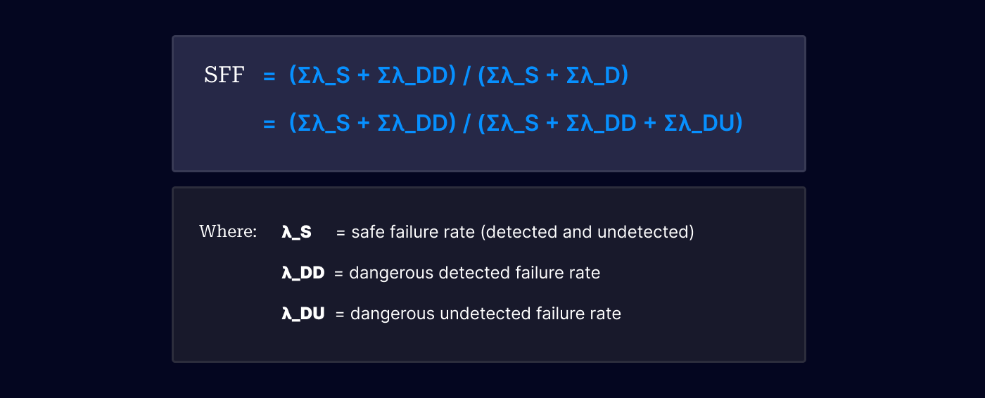
Safe Failure Fraction (SFF)
The SFF is the percentage of overall system failures that are classified as safe or are automatically detected by internal diagnostics. It directly dictates the architectural constraints of the system:
Probability of Failure
Depending on the system's concept of operations, hardware validation must meet specific probability envelopes:
Low-Demand Mode: Calculated via the Average Probability of Failure on Demand (PFD_avg), utilized when the safety loop is triggered less than once per year.
High-Demand / Continuous Mode: Calculated via the Probability of Failure per Hour (PFH), utilized when the safety function runs continuously or handles frequent operational triggers.
Engineering Management Checklist for Pillar Compliance
Lifecycle Integration: Verify that a defined safety management plan governs all 16 phases of the IEC 61508 framework from initial kickoff.
Analytical Alignment: Execute both bottom-up FMEAs and top-down FTAs to validate that no common-cause failures bypass design redundancies.
Quantitative Validation: Audit component reliability data to ensure that calculated SFF, PFDavg, and PFH limits satisfy target SIL parameters before final production sign-off.